Robotics Board
Robotics Board v0.8
A carrier board for the Milk-V Duo S that connects every robot device to the SG2000's C906 RISC-V core. The motor drivers, power conversion, IMU and safety chain are all on board; motors, sensors and servos plug in by cable.
At a glance
- Host
- Milk-V Duo SSG2000: A53 Linux + C906 RTOS
- Input
- 4S LiPo, 12–16.8 VXT30, 10 A fuse, reverse protection
- Wheel drivers
- 2 × DRV83133-phase, from the switched VMOT
- Logic rail
- 5.32 V / 5 ATPS54560 buck → Duo S VSYS
- Servo rail
- 6.0 V / 8 ALM61480 synchronous buck
- IMU
- Bosch BMI323I²C4, data-ready interrupt
- Angle sensors
- 4 × SPI portsAS5048A, 14-bit, own chip selects
- Safety
- Latched E-stop+ 10 ms watchdog, cuts VMOT
Architecture
There is no external microcontroller. The SG2000's C906 little core runs FreeRTOS: FOC for both wheels in a 10 kHz fast interrupt, the 400 Hz balance loop and the hip servos. Linux on the Cortex-A53 runs ROS 2 and talks to it through shared memory. The board routes every real-time signal to pins the C906 can own.
| Function | Part | Interface |
|---|---|---|
| Wheel motors | 2 × iPower GM4108H-120T (11 pole pairs, 11.1 Ω) | Phases on J2 (L) / J3 (R) |
| Wheel drivers | 2 × TI DRV8313 (U8 L, U9 R) | 3 PWM each, shared EN, nSLEEP, nRESET, wired-OR nFAULT |
| Rotor angle | AS5048A board shipped on each GM4108H | SPI 1 (J15), SPI 2 (J16) |
| Knee angle | AS5048A board on each knee axis | SPI 3 (J17), SPI 4 (J18) |
| Hip servos | 2 × DSSERVO DS3240 (40 kg·cm) | J20 / J21, 50–330 Hz PWM, 6 V |
| IMU | Bosch BMI323 (U10, 0x68) | I²C4 through a PCA9306, INT1 data-ready |
| Rail monitor | TI ADS1115 (0x48) | I²C4: VBUS, VSERVO, +5 V, VMOT |
| Accessory power | TPS16630 eFuse, TPS2553 switch | J24 battery out (2.5 A), J25 5 V out (0.5 A) |
| Expansion | Optional 3.3 V I²C display | J23 |
| Debug | Linux console, UART0 | J22 |
The right wheel runs on PWM controller 0 (3.3 V header J3) and the left wheel on controller 2 (1.8 V header J4, through a level translator), so each wheel's three phases update together. All four angle sensors share SPI3.
Connectors and pinouts
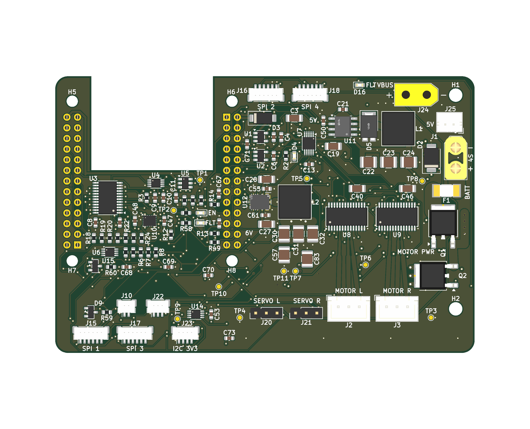
Pin 1 is marked on the silkscreen. Check every cable with a meter before first power-on: JST-SH and JST-XH leads are easy to build mirrored.
J1 · Battery in
XT30 male (XT30UPB-M), vertical. 12–16.8 V.
J2 / J3 · Motor phases
JST-XH 2.5 mm, 3 pins. Left / right wheel.
J15–J18 · SPI 1–4
JST-SH 1.0 mm, 6 pins, 3.3 V. Rotor L, rotor R, knee L, knee R (labels).
J20 / J21 · Servos
2.54 mm header, 3 pins, 6 V rail. Left / right hip.
J10 · E-stop loop
JST-SH, 2 pins. A normally-closed switch between them.
J22 · Debug UART0
JST-SH, 3 pins, 3.3 V logic, no power.
J23 · I²C display
JST-SH, 4 pins. 3.3 V devices only; shares the IMU bus.
J24 · Accessory battery out
XT30 female. 2.5 A limit, off while the E-stop is open.
J25 · Accessory 5 V out
JST-PH 2 pins. 0.5 A, logic power only.
Angle-sensor ports
All four ports are on one SPI3 bus with a chip select each. Depending on the production batch, a v0.8 board's silkscreen shows either the original names or SPI 1–4. The wiring is identical.
| Connector | Original label | Newer label | Sensor | Chip select |
|---|---|---|---|---|
| J15 | ROTOR L | SPI 1 | Left wheel motor AS5048A | B16 (SPI3_CS) |
| J16 | ROTOR R | SPI 2 | Right wheel motor AS5048A | B18 |
| J17 | KNEE L | SPI 3 | Left knee AS5048A | B22 |
| J18 | KNEE R | SPI 4 | Right knee AS5048A | B21 |
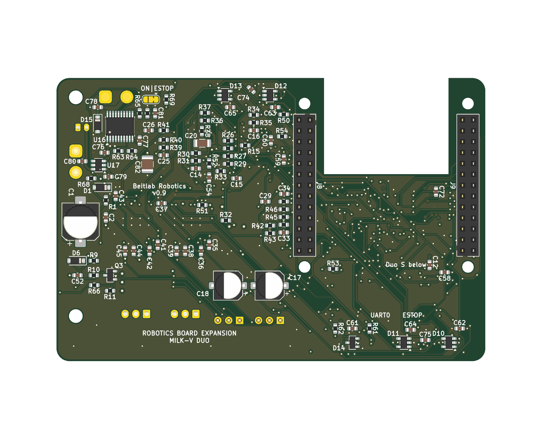
J8 and J9 are 2 × 13 sockets on the bottom side that take the Duo S's J3 (3.3 V) and J4 (1.8 V) headers. The board sits about 11 mm above the Duo S on four M2.5 standoffs. Two M3 holes on the right edge (H1, H2) fix the stack to the chassis.
Power
| Rail | Source | Peak load | Notes |
|---|---|---|---|
VBUS 12–16.8 V | 4S pack, 10 A NANO2 fuse, AOD4185 PMOS | ≈ 8 A (≈ 10 A with J24 at its limit) | SMBJ20A TVS, 220 µF bulk |
VMOT | VBUS through Q2, on only while the E-stop latch is set | ≈ 3 A, both motors | Soft ramp, about 30 V/ms |
VSERVO 6.0 V | LM61480 buck, 8 A | 2 × 3.5 A stall | A double stall is fine for seconds, not continuously |
+5V 5.32 V | TPS54560 buck, 5 A | ≈ 1.2 A + J25 | Feeds Duo S VSYS through a Schottky, about 4.9–5.0 V |
+3V3 | AP2112K-3.3 | ≈ 90 mA | Sensors, IMU, ADC, logic |
+1V8 | AP2112K-1.8 | < 5 mA | Level-translator references |
About 260 µF of input capacitance charges through Q1's body diode when the pack is connected, so expect a spark at the XT30. Use an anti-spark lead, a 10 Ω pre-charge resistor bridged out after a second, or a battery switch that is closed last. The E-stop cuts motor power, not the battery: fit a physical battery disconnect as well.
Torque budget. The GM4108H is a direct-drive gimbal motor. With the firmware's 1.5 A current clamp, expect about 0.15 N·m per wheel. With the robot's 84.8 mm wheels that is enough to recover from a lean of roughly 20°, not for fast get-ups: keep the robot light. There is no current sensing; torque is set through a motor model, so measure R, Ke and the zero electrical angle on every motor.
Safety chain
Motor enable is decided in hardware, independently of software:
MOT_EN = MOT_EN_REQ AND WDT_OK AND ESTOP_RUN # 74LVC1G11 → both DRV8313 EN pins- Watchdog (WDT_OK). A 74LVC1G123 retriggerable one-shot of about 10 ms. The C906 toggles
WDT_KICKon every 400 Hz balance tick. It triggers on edges, so a hung core holding the pin high or low drops EN within about 10 ms. - E-stop latch (ESTOP_RUN). A 74AUP1G74 flip-flop. Opening the normally-closed loop on J10, or unplugging it, clears the latch at once: EN drops and Q2 cuts VMOT within about 2 ms. A bouncing switch cannot set it again. Only a rising
ESTOP_ARMedge from firmware, withMOT_EN_REQhigh and the loop closed, re-arms it. - Safe at power-up. A supervisor (U15) holds the latch clear through startup and brownouts, and every control line has a pull-down. The drivers stay asleep and disabled while Linux boots.
- Accessory output. J24 follows the E-stop latch by default (jumper JP1, pads 1–2). Moving it to 2–3 keeps J24 on whenever the board is powered: do that only deliberately.
- The servo rail is not cut by the E-stop, because cutting knee power would drop the robot. The servo-hold policy on faults is a firmware decision.
Status LEDs and test points
| Indicator | Meaning |
|---|---|
| D4, green | Board powered |
D7, yellow, EN | MOT_EN high: the motors are enabled |
D8, red, FLT | A DRV8313 is reporting a fault (nFAULT low) |
D16, red, FLT VBUS | J24 or J25 fault: overload, over-temperature, over/under-voltage or back-feed |
| Test point | Net | Test point | Net |
|---|---|---|---|
| TP1 | WDT_OK | TP2 | MOT_EN |
| TP3, TP4, TP11 | GND | TP5 | VBUS |
| TP6 | VMOT | TP7 | VSERVO |
| TP8 | +5V | TP9 | ESTOP_RUN |
| TP10 | DRV_NFAULT |
Reference documents
Full schematic
Every sheet of the frozen v0.9 design.
PDF · 419 KB ReportSubsystems
Block diagrams, board maps, derived values and measured layout checks.
PDF · 276 KB ReportCircuit drawings
Each subsystem with standard symbols, checked against the netlist.
PDF · 200 KB