Balance Robot v1
Balance Robot v1
A two-wheeled balancing biped with adjustable legs. One servo per leg sets the height through a four-bar linkage that keeps the wheel under the hip, and two direct-drive brushless motors keep the robot upright.
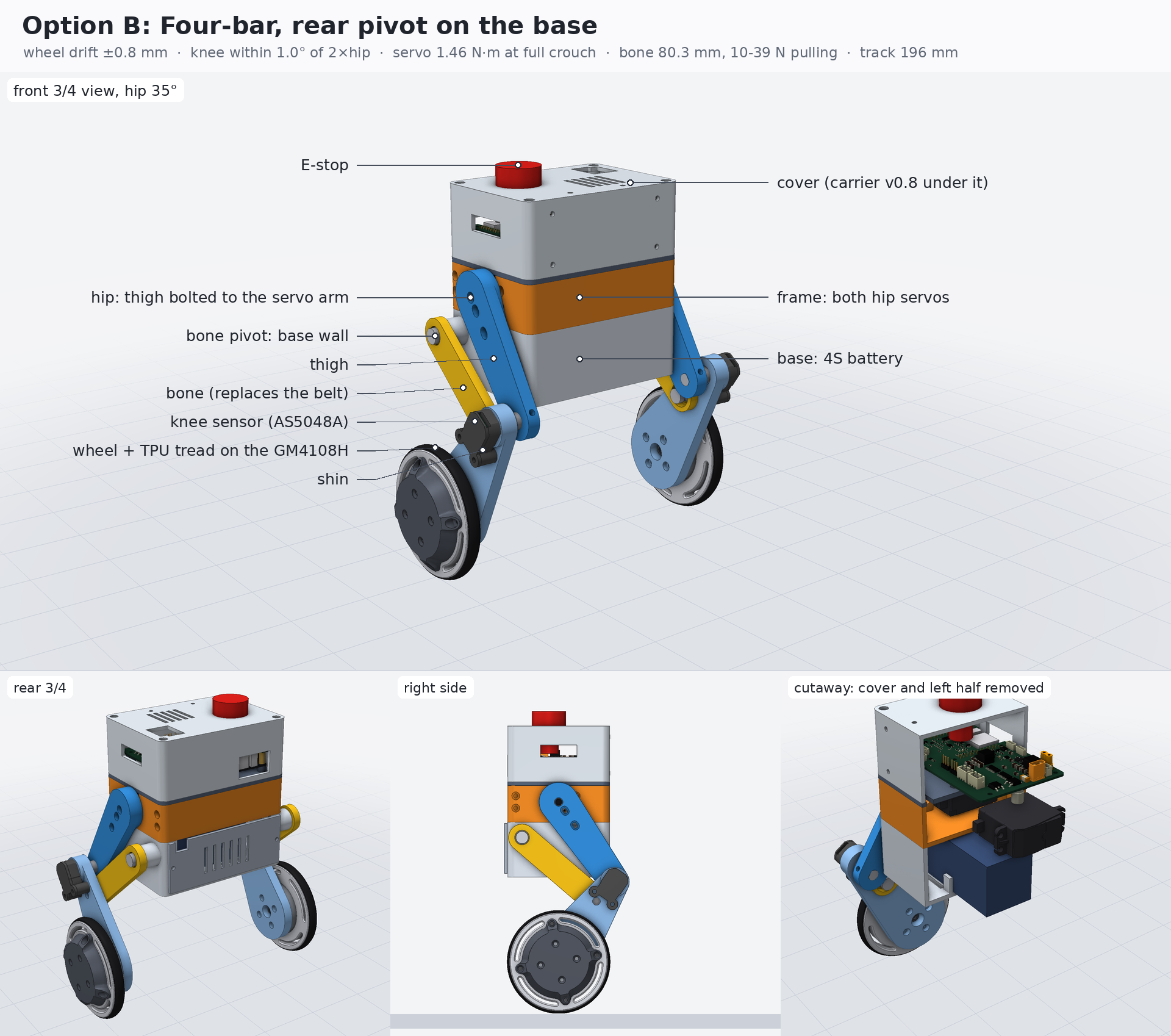
Specifications
- Height
- 195–259 mmto the cover, by crouch; E-stop +12 mm
- Body
- 116 × 84 × 124 mmfour 3D-printed sections
- Track
- 196 mmwheel centre to centre
- Wheels
- Ø 84.8 mmTPU tread on a printed rim
- Pitching body
- 1.19 kgwithout wheels, from CAD
- Wheel motors
- 2 × GM4108H-120Tdirect drive, ≈ 0.15 N·m each
- Leg actuators
- 2 × DS324040 kg·cm, at the hips
- Battery
- 4S LiPo75 × 37 × 38 mm default pack
- Computer
- Milk-V Duo Son the Robotics Board v0.8
- Hip range
- 15–55°knee 30–110°
Masses are design values from the CAD with estimates for bought parts. Replace them with weighed values before designing real gains.
Layout
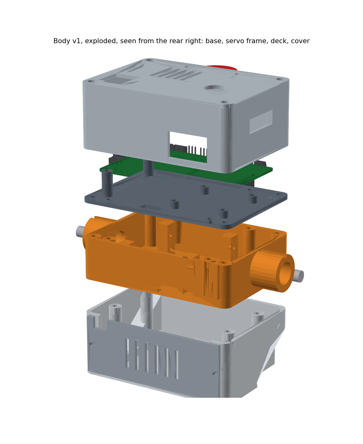
The body is a stack of four printed parts, bottom to top. Axes: X lateral (+ right), Y forward, Z up from the underside of the body.
| Z (mm) | Part | Holds |
|---|---|---|
| 0–45 | Base and battery door | The 4S pack, loaded from the rear on two velcro straps; two external pivot bosses for the legs' bones |
| 45–75 | Frame | Both DS3240 servos on their sides, back to back, screwed to the side walls from outside |
| 75–78 | Deck | Bosses for the Duo S and the Robotics Board, a slot for the servo leads |
| 78–124 | Cover | E-stop, openings for the power connectors and the Duo S's RJ45 and USB-A, vents, six M3 accessory mounts |
The board sits turned 180°: its power entry and the Duo S ports face the rear, and the motor, servo, sensor, E-stop and console connectors face the front. The cover has six M3 accessory points (four on the front face, two on top) with captive nuts, for a sensor, camera, bumper or handle.
The four-bar leg
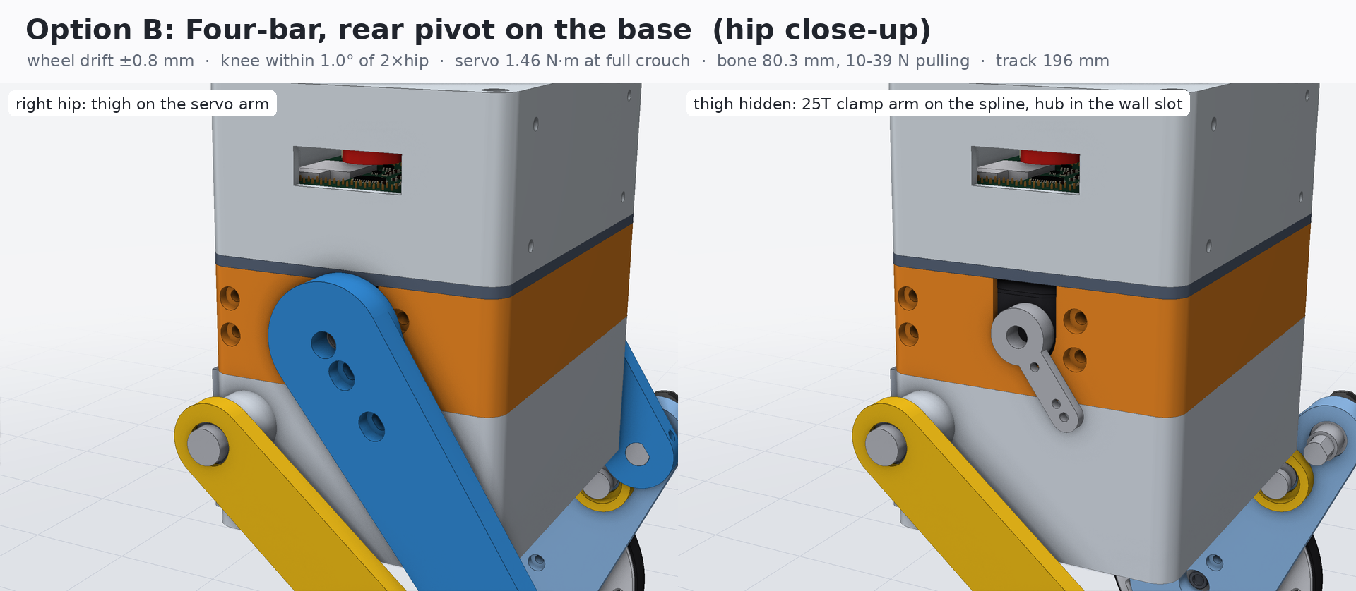
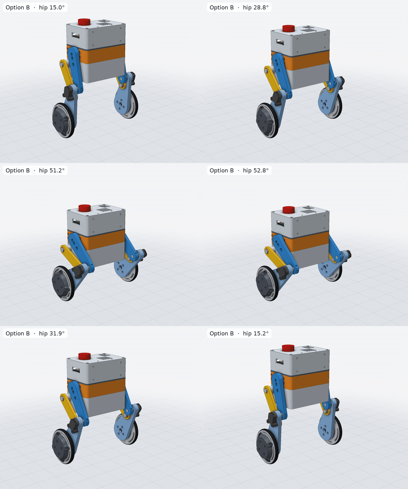
Each thigh bolts straight onto its servo's 25T aluminium clamp arm; there is no hip shaft or hip bearing. A printed “bone” runs from a pivot on the base wall to the shin. Together they form a four-bar linkage that keeps the knee within 1° of twice the hip angle, and the wheel within 0.8 mm of directly under the hip, across the whole range.
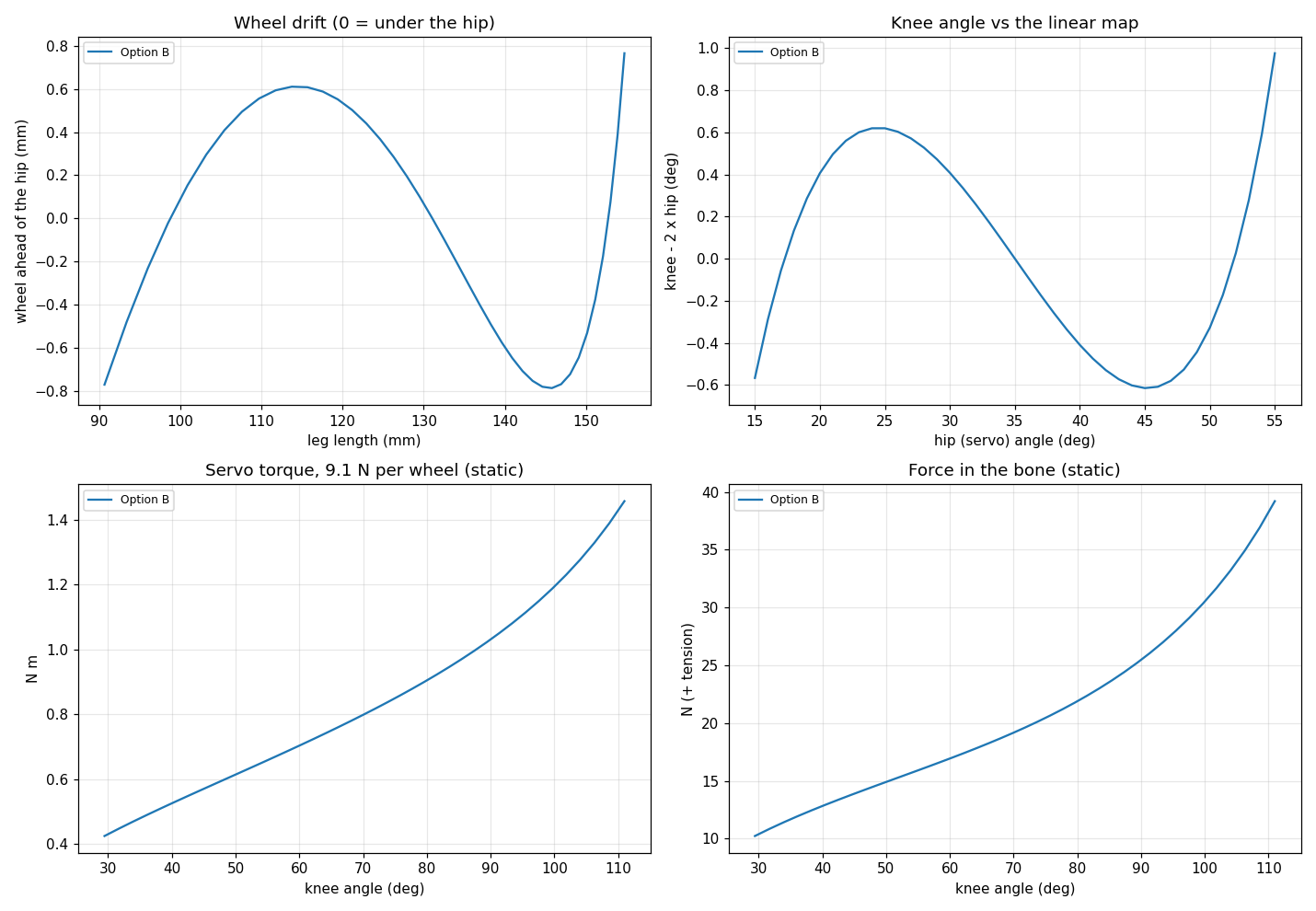
Because the wheel stays under the hip, the controller can treat leg length as height, and the servo pulse map stays linear after calibration. The cost is torque: the servo needs up to about 1.46 N·m static at full crouch, around 37 % of its stall torque. Each knee carries an AS5048A angle sensor, so the controller measures the leg rather than trusting the servo command. A servo that fails to track latches a fault instead of corrupting the gain schedule.
Mass and centre of mass
The centre of mass sits below the hip, which needs less wheel torque but falls faster. The LQR delay margin is 1–2 ticks of 2.5 ms.
| Hip / knee | CoM above axle | CoM relative to hip |
|---|---|---|
| 15° / 30° (tall) | 108 mm | 47 mm below |
| 35° / 70° | 91 mm | 40 mm below |
| 55° / 110° (crouch) | 62 mm | 29 mm below |
Control
The balance state is wheel position and speed relative to their references, body pitch and pitch rate. A gain-scheduled LQR, with the gains interpolated across leg heights, computes the total wheel torque; a yaw term from the gyro splits it between the wheels.
- STAND balances from an upright pose at a height set from Linux. CROUCH goes to the minimum height. DRIVE follows speed and yaw-rate commands. RECOVERY disables the outputs: autonomous get-up is not implemented.
- Arming requires an upright estimate and a commissioned configuration. Faults latch; reset needs a fresh, disarmed command and an upright robot, then a separate arm request.
- There is intentionally no default gain table. Gains are designed offline from measured mass properties with
tools/control/design_lqr.py.
Simulation
The URDF, ROS 2 description and Isaac Sim asset are generated from the same CAD. The firmware controller runs in the loop on the host, and Isaac Lab tasks train balance, velocity-tracking and leg policies with terrain curricula and domain randomization. Policies export to C arrays for comparison with the LQR. To view the model on your PC, see First steps.
CAD files
Whole robot
Option B at hip 30°, without the board. Opens in Onshape and FreeCAD.
STEP · 6.8 MB STEPFully mounted
The same, with all 134 screws, inserts, bearings, washers, standoffs and magnets.
STEP · 12.0 MB BOMHardware list
Every bought part in the mounted model, counted and located.
Text · 2 KB STLPrinted parts
Every part in print orientation, with quantities and notes.